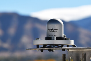
Detector Type
Silicon-cell
Classification
ISO 9060:2018 Class C
Spectral Range
360 to 1120 nm
Response Time
Less than 1 ms
Error Due to Clouds
+10 to 15 % (common to all silicon-cell pyranometers)
Heated Option
SP-230 All-Season pyranometer has a 0.2 W heater
Output Options
Available in multiple analog and digital outputs including unamplified, SDI-12, and Modbus communication protocols. It can also be attached to a hand-held meter with a digital readout
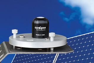
Detector Type
Blackbody Thermopile
Classification
ISO 9060:2018 Class C
Spectral Range
Upward-looking (SP-510): 385 to 2105 nm
Downward-looking (SP-610): 295 to 2685 nm
Response Time
0.5 seconds
Error Due to Clouds
± 2 %
Heated Option
Sensors have a 0.2 W heater
Output Options
Available in analog output and Modbus communication protocols
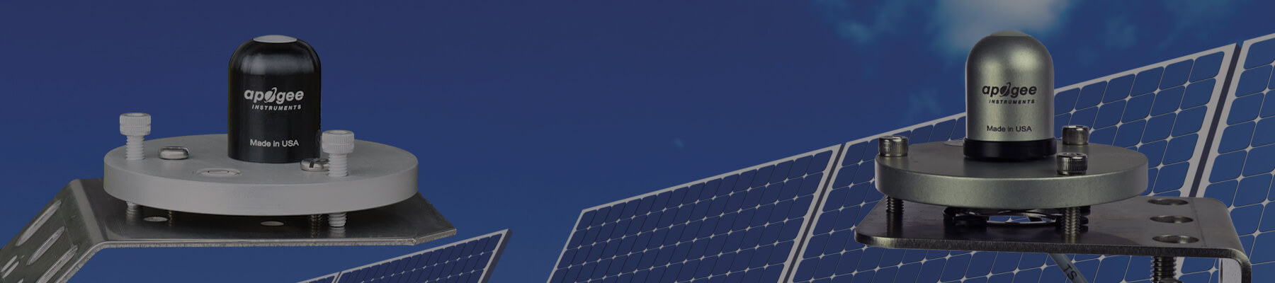
Upward- and Downward-looking Options
The upward-looking (SP-510) and downward-looking (SP-610) models can be mounted back-to-back to make an albedometer using the AL-120 mounting bracket