All objects with a temperature above absolute zero emit electromagnetic radiation. The wavelengths and intensity of radiation emitted are related to the temperature of the object. Terrestrial surfaces (e.g., soil, plant canopies, water, snow) emit radiation in the mid infrared portion of the electromagnetic spectrum (approximately 4-50 µm).
Infrared radiometers are sensors that measure infrared radiation, which is used to determine surface temperature without touching the surface (when using sensors that must be in contact with the surface, it can be difficult to maintain thermal equilibrium without altering surface temperature). Infrared radiometers are often called infrared thermometers because temperature is the desired quantity, even though the sensors detect radiation.
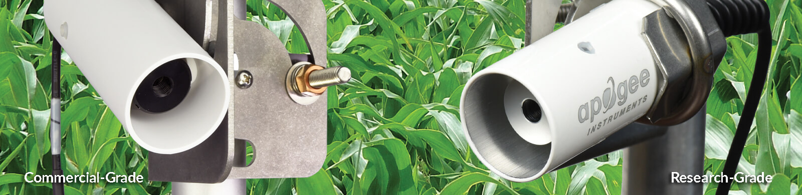
Apogee Instruments SI series infrared radiometers consist of a thermopile detector, germanium filter, precision thermistor (for detector reference temperature measurement), and signal processing circuitry mounted in an anodized aluminum housing, and a cable to connect the sensor to a measurement device. All radiometers also come with a radiation shield designed to minimize absorbed solar radiation, but still allowing natural ventilation. The radiation shield insulates the radiometer from rapid temperature changes and keeps the temperature of the radiometer closer to the target temperature. Sensors are potted solid with no internal air space and are designed for continuous temperature measurement of terrestrial surfaces in indoor and outdoor environments.
| SI-111-SS | SIL-111 | SI-121-SS | SI-131-SS | SI-1H1-SS | |
|---|---|---|---|---|---|
| Analog Model Output (Difference between Target and Detector) | 50 µV per C | 50 µV per C | 30 µV per C | 15 µV per C | 30 µV per C |
| Thermistor Input Voltage Requirement | 2500 mV excitation (typical, other voltages can be used) | 2500 mV excitation (typical, other voltages can be used) | 2500 mV excitation (typical, other voltages can be used) | 2500 mV excitation (typical, other voltages can be used) | 2500 mV excitation (typical, other voltages can be used) |
| Analog Output from Thermistor | 0 to 2500 mV (typical, depends on input voltage) | 0 to 2500 mV (typical, depends on input voltage) | 0 to 2500 mV (typical, depends on input voltage) | 0 to 2500 mV (typical, depends on input voltage) | 0 to 2500 mV (typical, depends on input voltage) |
| Calibration Uncertainty (0 to 50 C), when target and detector ΔT are < 20 C | 0.2 C | 0.5 C | 0.2 C | 0.3 C | 0.2 C |
| Calibration Uncertainty (-30 to 65 C), when target and detector ΔT are < 20 C | 0.2 C | - | 0.2 C | 0.3 C | 0.2 C |
| Calibration Uncertainty (-40 to 80 C), when target and detector ΔT are < 20 C | 0.5 C | - | 0.5 C | 0.6 C | 0.5 C |
| Measurement Repeatability | Less than 0.05 C | Less than 0.05 C | Less than 0.05 C | Less than 0.05 C | Less than 0.05 C |
| Response Time (time for detector signal to reach 95 % following a step change) | 0.6 s | 0.6 s | 0.6 s | 0.6 s | 0.6 s |
| Field of View | 22° half-angle | 22° half-angle | 18° half-angle | 14° half-angle | 32° horizontal half-angle, 13° vertical half-angle |
| Spectral Range | 8 to 14 µm atmospheric window | 8 to 14 µm atmospheric window | 8 to 14 µm atmospheric window | 8 to 14 µm atmospheric window | 8 to 14 µm atmospheric window |
| Operating Environment | -50 to 80 C, 0 to 100 % relative humidity (non-condensing) | -50 to 80 C, 0 to 100 % relative humidity (non-condensing) | -50 to 80 C, 0 to 100 % relative humidity (non-condensing) | -50 to 80 C, 0 to 100 % relative humidity (non-condensing) | -50 to 80 C, 0 to 100 % relative humidity (non-condensing) |
| Mass | 190 g | 190 g | 190 g | 190 g | 190 g |
| SI-411-SS | SI-421-SS | SI-431-SS | SI-4H1-SS | SI-4HR-SS | SI-511-SS | SI-521-SS | SI-531-SS | SI-5H1-SS | SI-5HR-SS | SIL-411 | |
|---|---|---|---|---|---|---|---|---|---|---|---|
| Digital Input Voltage Requirement | 5.5 to 24 V DC | 5.5 to 24 V DC | 5.5 to 24 V DC | 5.5 to 24 V DC | 5.5 to 24 V DC | 5.5 to 24 V DC | 5.5 to 24 V DC | 5.5 to 24 V DC | 5.5 to 24 V DC | 5.5 to 24 V DC | 5.5 to 24 V DC |
| Average Current Draw | 1.5 mA (quiescent), 2.0 mA (active) | 1.5 mA (quiescent), 2.0 mA (active) | 1.5 mA (quiescent), 2.0 mA (active) | 1.5 mA (quiescent), 2.0 mA (active) | 1.5 mA (quiescent), 2.0 mA (active) | RS-232 quiescent 37 mA, active 37 mA; RS-485 quiescent 37, active 42 mA |
RS-232 quiescent 37 mA, active 37 mA; RS-485 quiescent 37, active 42 mA |
RS-232 quiescent 37 mA, active 37 mA; RS-485 quiescent 37, active 42 mA |
RS-232 quiescent 37 mA, active 37 mA; RS-485 quiescent 37, active 42 mA |
RS-232 quiescent 29 mA; RS-485 30 mA |
1.5 mA (quiescent), 2.0 mA (active) |
| Calibration Uncertainty (0 to 50 C), when target and detector ΔT are < 20 C | 0.2 C | 0.2 C | 0.3 C | 0.2 C | 0.3 C | 0.2 C | 0.2 C | 0.3 C | 0.2 C | 0.5 C | 0.5 C |
| Calibration Uncertainty (-30 to 65 C), when target and detector ΔT are < 20 C | 0.2 C | 0.2 C | 0.3 C | 0.2 C | 0.3 C | 0.2 C | 0.2 C | 0.3 C | 0.2 C | 0.5 C | - |
| Calibration Uncertainty (-40 to 80 C), when target and detector ΔT are < 20 C | 0.5 C | 0.5 C | 0.6 C | 0.5 C | 0.5 C | 0.5 C | 0.5 C | 0.6 C | 0.5 C | 1 C | - |
| Measurement Repeatability | Less than 0.05 C | Less than 0.05 C | Less than 0.05 C | Less than 0.05 C | Less than 0.05 C | Less than 0.05 C | Less than 0.05 C | Less than 0.05 C | Less than 0.05 C | Less than 0.05 C | Less than 0.05 C |
| Response Time (time for detector signal to reach 95 % following a step change) | 0.6 s | 0.6 s | 0.6 s | 0.6 s | 0.6 s | - | - | - | - | - | 0.6 s |
| Field of View | 22° half-angle | 18° half-angle | 14° half-angle | 32° horizontal half-angle, 13° vertical half-angle | 16° horizontal half-angle, 5° vertical half-angle | 22° half-angle | 18° half-angle | 14° half-angle | 32° horizontal half-angle, 13° vertical half-angle | 16° horizontal half-angle, 5° vertical half-angle | 22° half-angle |
| Spectral Range | 8 to 14 µm atmospheric window | 8 to 14 µm atmospheric window | 8 to 14 µm atmospheric window | 8 to 14 µm atmospheric window | 8 to 14 µm atmospheric window | 8 to 14 µm atmospheric window | 8 to 14 µm atmospheric window | 8 to 14 µm atmospheric window | 8 to 14 µm atmospheric window | 8 to 14 µm atmospheric window | 8 to 14 µm atmospheric window |
| Operating Environment | -50 to 80 C, 0 to 100 % relative humidity (non-condensing) | -50 to 80 C, 0 to 100 % relative humidity (non-condensing) | -50 to 80 C, 0 to 100 % relative humidity (non-condensing) | -50 to 80 C, 0 to 100 % relative humidity (non-condensing) | -50 to 80 C, 0 to 100 % relative humidity (non-condensing) | -50 to 80 C, 0 to 100 % relative humidity (non-condensing) | -50 to 80 C, 0 to 100 % relative humidity (non-condensing) | -50 to 80 C, 0 to 100 % relative humidity (non-condensing) | -50 to 80 C, 0 to 100 % relative humidity (non-condensing) | -50 to 80 C, 0 to 100 % relative humidity (non-condensing) | -50 to 80 C, 0 to 100 % relative humidity (non-condensing) |
| Mass (with 5 m of cable) | 190 g | 190 g | 190 g | 190 g | 219 g | 190 g | 190 g | 190 g | 190 g | 219 g | 190 g |
How to Choose an Infrared Radiometer
If you can't access the video via Youtube, click here.
Brief Overview of Infrared Radiometers
If you can't access the video via Youtube, click here.
Webinar: Infrared Insights by Ryan Lindsley
Principles of Surface Temperature Measurement
If you can't access the video via Youtube, click here.
Using Infrared Radiometers for Plant Science Research
If you can't access the video via Youtube, click here.
Lecture 2-Infrared Surface Temperature
Typical applications of infrared radiometers include:
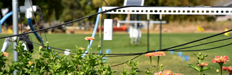
• Phenotyping
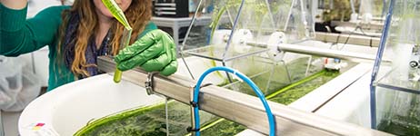
• Plant canopy temperature measurement for use in plant water status estimation
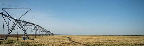
• Road surface temperature measurement for determination of icing conditions
• Terrestrial surface (soil, vegetation, water, snow) temperature measurement in energy balance studies


")

")


If you would like to share your application of this product, please click here.
Applications and references of Infrared Radiometers
FOV & Canopy Fraction Calculators
Estimating the Canopy Fraction in Your IR FOV
Excel Sheet programmed to calculate target area
Design and Calibration of Infrared Radiometer
IR SI Radiation Shield: More Information
Horizontal FOV Infrared Radiometer: More Information
Apogee Meter Tips and Troubleshooting
Protecting Your Instruments from Spiders, Wasps, and Other Pests
Emissivity Correction for Infrared Radiometer Sensors
LoggerNet Short Cut Instructions
How to take IR Temperature Measurements without a Datalogger
Minimize Losses from Frost Using Direct Measurements - Campbell Scientific Blog Post
Using Infrared Thermometers for Plant Science Research
Infrared Thermometers for Monitoring Plant Temperatures in Greenhouses
Programs are in .CR1X format and can be downloaded for use with Campbell Scientific dataloggers. Right click and select "Save target as..." or an equivalent command in your browser. They can also be viewed using Wordpad or other text viewers.
Note: In 2020 the CR1000 Campbell Scientific datalogger was discontinued. Click here to access the discontinued .CR1 format sample datalogger programs >

